Keep it simple for ADAS dummies
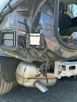
Sometimes, what appears to be a complex issue turns out to be a simple, albeit puzzling, one. I was called to a shop on a 2023 Honda CR-V having an issue with a blind spot monitoring system (Figure 1). The vehicle was involved in a rear end collision, and the left rear quarter panel of the vehicle took a direct hit from the accident. The shop had to replace the module because it had minor damage to the housing. Once these modules take a direct hit there may be liabilities if you decide to reuse them. I have even seen some radar modules on other manufactures that had the labeling “If dropped, dispose,” so it’s a strong indication that the internal circuit may be compromised and may not be able to process data inputs properly. The shop made the right choice to replace the module but there were issues with the new module creating error codes in the system. The shop decided to call me in for a possible reprogramming of the new module or to see if there were some underlying issues with the rear body harness he had overlooked.
Prior to arriving there, I made sure the rear bumper of the vehicle was left off so I could inspect the rear body harness, if needed. This tactic could save a lot of time, considering the removal process of some bumpers may get a little involved. I did not want to waste most of my diagnostic time helping the shop remove the bumper while I was there.
Scan to assess vehicle system health
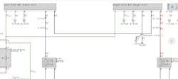
When I arrived at the shop, I performed a full vehicle scan on the car to get an overview of the vehicle just to make sure there were not any other underlying issues in the ADAS network and to validate that I could communicate with each rear blind spot control module. The left blind spot module had two current codes in memory, while the right-side blind spot module had no codes in memory. The first code was a B18C7 for an open in the left-side blind spot indicator circuit. The second code was a U1297 for the left-side blind spot module losing communication with the right-side blind spot module (Figure 2).
I pulled the wire conduit and black tape back a little to do a visual inspection on the harness. Without a diagram, I was able to guesstimate the role of most of these wires using my experience of doing so many blind spot modules. There is that old saying, “You don’t know what you don’t know.” If you can identify within these circuits what you definitely know, then the rest is what you don’t know. At this point, you are going to need a diagram to figure out the unknown. I knew the twisted red and white wires were the CAN network lines, the black wire was most likely a ground, but the light green and the light blue wires had to be power feed and the indicator circuit feeding back to the blind spot bulb for the side mirror (Figure 3).
Consult a wiring diagram to confirm functions
At this point, I did not want to ground the wrong wire to illuminate the indicator bulb because there was a chance of blowing the fuse that fed the blind spot module. I went to AllData to print out the wiring diagram, which gave me a good overview of the system to properly perform my testing on the harness connector (Figure 4). I now knew for sure that the light green wire on pin #1 was the power source for both blind spot modules and the light blue wire on pin #2 was the indicator circuit leading back to the side mirror indicator light bulb.
You CAN do it
I unplugged the new blind spot module and proceeded to check the wiring with my Power Probe. The two CAN lines showed proper voltage, so I knew that the CAN lines were neither shorted nor open. They were within 0.2-0.3 volts of each other, the ground was at about 100 millivolts, and the power feed was at about 12 volts. But the indicator circuit was an open circuit because there should have been a 12-volt reading feeding back from the indicator bulb. As this car was new, I felt the problem had to be somewhere in the rear harness. But I wanted to move forward on the CAN network issue because it posed a larger problem. The shop’s technician had told me that he felt that maybe the new part was bad, so he swapped the parts side-to-side. But now, the same error codes moved to the right side of the vehicle, with codes for the right blind spot indicator open circuit and the right-side blind spot module not communicating with the left blind spot module.
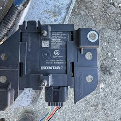
This whole situation seemed very odd, so we took both parts out and flipped them over to compare part numbers for a possible changed part number that was not compatible, or maybe they are required to be changed in pairs. The new module on the left side of the vehicle had a part number of 682174200A (Figure 5), but the one on the right side of the vehicle had a part number of 682677200A, which was a totally different number altogether.
Finding the DUMMY
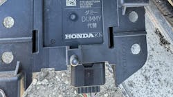
After a close inspection of the right-side part number, something caught the eyes of the owner of the body shop and me. We saw the word “Dummy” stamped on the right blind spot module that the new part was not stamped with (Figure 6). This right-side blind spot module was just a placeholder and only served to seal off the connector to keep out moisture. It also would not interact with the ADAS system because this particular car never came with the blind spot module option. When the new non-DUMMY module was installed on the left side of the vehicle, it woke up the system and put a blind spot error on the instrument cluster. To add to this further, there were no blind spot indicators in the side mirrors (Figure 7). This was why the new module would set an Indicator code for either side in conjunction with setting a CAN network code when it was plugged in. So, the only fix was to buy another dummy.
What an unbelievable situation to happen in the industry, all because the shop was given the wrong module! The part was ordered by VIN, but somehow the blind spot option question was overlooked. It makes you wonder why a manufacturer would not just use a dummy plug instead to avoid all this "rabbit hole journey” and confusion that I’m sure other shops will fall into. It all goes back to my old-school teachings from watching Sesame Street when I was a little kid, singing “One of These Things is Not Like the Others.” It is so important today to really take the time out to compare new parts with the old ones to make sure you’re not handed the wrong part that could waste a lot of your cycle time in getting these jobs out the door. Keep it simple by performing a visual inspection to make sure the part number is the same, connector pin configurations look identical and in order, and even the mounting looks the same. The parts guy may even tell you that there’s been a changed part number, but it’s up to you to do the final evaluation. I’m hoping that this story hits home with a lot of you auto body techs out there, and all I can say is, “buyer beware.”


