Is that voltage reading really unusual?
From time to time you will measure a voltage and anticipate what the approximate reading should be only to find the reading is completely different from what you expected. The first thing to do when this happens is make sure you are not making a mistake. Follow these simple steps to eliminate human error.
(1) NEVER ASSUME ANYTHING!
(2) Confirm the DMM is set to the proper function, DCV (DC volts).
(3) Confirm a battery symbol is NOT displayed in the DMM readout indicating the DMM’s internal 9 V battery is weak. Stop! Change the 9 V battery. When the battery symbol appears a DMM indicates a higher voltage than what is in the circuit.
(4) Confirm the DMM is properly grounded to -BATT or -GEN.
(5) Confirm the red test lead is connected to the V/Ω jack.
(6) Confirm the red test lead is touching the correct test point in the circuit.
Still have an unusual reading? It’s not you. It is a reflection of what is going on in the circuit from an electrical point of view. Remember circuits ALWAYS obey the laws of electrical circuits which is fundamental to the operation of the Universe. The United States has built spacecraft on the Earth and placed a robot on the Martian surface that takes pictures and sends them back to us on Earth. The various electrical and electronic circuits that were designed on earth according to the Universal Laws of series and parallel circuits still works the same on the planet Mars as it did on Earth. As we reach father out into the universe, spacecraft instruments covering the surface of a new planet will work just like they did on earth and on Mars. Series and parallel circuits always work the same way and get this! They all fail the same various ways. It doesn’t matter to an electrical circuit if it is in a robot on the surface of Mars or in your customer’s vehicle, circuits all fail the same number of ways. This can be a major topic of discussion that we can’t cover in detail here, but I will tell you this much. The ways that circuits fail are: (1) open connections or components; (2) change in component resistance (voltage drops); (3) short to ground; (4) short to voltage.
If you want to pursue more training on electrical circuits, how they work, how circuits fail and how to troubleshoot electrical circuits, I suggest you consider our hands-on electrical training program beginning with the Starter Kit, H-111A. There is an explanation, picture and a purchase link lower in this email.
A series circuit will always act like a series circuit. A parallel circuit will always act like a parallel circuit regardless of the planet it is on. A compound circuit containing both series and parallel will always act like a compound circuit. It’s up to us to know what happens to voltage, electron current and resistance in a series circuit or a parallel circuit. Then we can understand the operation of a compound circuit containing both series and parallel.
If you want to pursue more training on series and parallel electrical circuits to improve your knowledge, then I suggest you take a look at our 60-lesson home study course. The first 18 lessons cover this topic in great detail. There is a link lower in this email to read about the 60 lessons.
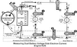
Before we look at some unusual DMM readings you should have a firm grasp on what normal readings should be. Below in Figure G14V-1 we illustrate five ground side circuit voltage checks. (A “Circuit voltage” means the DMM is grounded to -BATT or -GEN.)
The DMM is grounded at -BATT in Figure G14V-1. We could just as easily ground the DMM at -GEN and get the same results. There are five circuits and five ground side voltage measurements. The DMM is set to the 20 V range and the display indicates 0.00 before voltage measurements are taken. Below are the 5 DMM ground circuit readings in this vehicle. (Reminder: A good electrical circuit ground circuit is 0.10V or less.
A good on-board computer ground is 0.05V or less.)
DMM#1 DMM#2 DMM#3 DMM#4 DMM#5
0.04V 0.04V 0.05V 0.05V 0.18V
Questions (Answers at the end of the article)
Question 1: What three possible faults could cause DMM #5 to be higher than normal?
[1]
[2]
[3]
Question 2: What parts or sections of the circuit are known to be good based on the other four readings?
[1]
[2]
[3]
In Figure G14V-2 we illustrate how a ground strap failure could be detected.
In checking the ground side voltage, the DMM readings at circuits #3, #4 and #5 show a common voltage problem on the ground side. In this example, last 3 DMM readings are higher than normal which accounts for the poor performance of the three circuit loads and the three lamps are dim. There is a common problem affecting all three circuits and it is found to be on the ground side. The three loads are lamps so they are dim. If the three loads were solenoids they would act sluggish. If the three loads were DC motors they would operate at a lower RPM (turn slower).
DMM#1: 0.04V DMM#2: 0.04V DMM#3: 0.87V DMM#4: 0.85V DMM#5: 0.86V
Circuits are drawn with a ground symbol and maybe a ground number is added. Sometimes the circuit’s ground symbol is not numbered and a ground strap is not always shown on a schematic diagram to complete the ground circuit. The physical location of the ground strap may not be known from the schematic. If no ground strap is indicated on the schematic diagram then physically inspect sheet metal (2) looking for a ground strap or how sheet metal (2) is connected (bolted) to sheet metal (1). In Figure G14V-2 above, the ground strap has some corrosion causing sheet metal (2) to exist at about 0.85V instead of a normal 0.05V – 0.10V. The quality of the ground voltage at sheet metal (2) can be confirmed by placing the red test lead on sheet metal (2). The DMM indicates 0.85V. Since sheet metal (1) has a normal ground voltage of 0.04V DMM#1 and DMM#2 OK), the ground strap has to be corroded or damaged. Clean and reassemble both terminals of the ground strap and test again.
Question 3: What would DMM#3 indicate if Switch S3 were switched OFF?
Question 4: If Switches S3, S4 and S5 are turned OFF, what would be the ground voltage on sheet metal (2)?
In Figure G14V-3 we discover an unusual voltage reading in Circuit #4.
Here are the circuit conditions. The engine is running. Switch S4 is OFF (not closed). Lamp Circuit #4 is not operating. The DMM red test lead is measuring the voltage at Circuit #4 Pin 2.
Question 5: What is the voltage you expect to be measured at Circuit #4 Pin 2?
In Figure G14V-4 we discover another unusual voltage reading in Circuit #2.
Here are the circuit conditions. The engine is running. Switch S2 is OFF (not closed). Lamp Circuit #2 is not operating. The DMM red test lead is measuring the voltage at Circuit #2 Pin 2 and Pin 1.
Question 6: What is the voltage you expect to be measured at Circuit #2 Pin 2.?
Question 7: What is the voltage you expect to be measured at Circuit #2 Pin 1?
Answers
Answer 1: [1] corroded connection at G302; [2] damaged or corroded ground wire; [3] Circuit #5 drawing excessive electron current. (The wire diameter for the ground circuit of Circuit #5 is determined by the normal electron current drawn through Circuit #5. If the circuit load, the lamp, were to begin drawing too much current due to a loss in resistance, the increased electron current through the wire can be expected to cause a higher-than-normal Vd (Voltage drop) across the ground circuit wire.)
Answer 2: [1] sheet metal (2) provides a good ground to the 3 circuits; [2] the ground strap is good and [3] sheet metal (1) is grounded through the accessory ground cable to -BATT.
Answer 3: Whatever the ground side voltage value is present at sheet metal (2) would appear at Circuit #3 Pin 2.
Answer 4: 0.04V, the same as the voltage on sheet metal (1). Since circuits #3, #4 and #5 are turned OFF there is no circuit electron current through the corroded ground strap. Since there is no current through the ground strap there is no voltage drop across the ground strap. But since it is connected to sheet metal (1) you can read the voltage on sheet metal (1) at sheet metal (2). They are connected together.
Important Rule of Troubleshooting Electrical:
You cannot check the quality of a ground circuit if the circuit is turned OFF. The circuit must be turned ON and electron current flowing (circuit is intact between B+ and B- so electrons are flowing) when checking the voltage at a ground point anywhere on a vehicle. (NO current = NO Vd.)
Answer 5: The voltage at Pin 2 is B+ since the engine is running the B+ is the charging voltage of the vehicle which is 14.2 V for purposes of this discussion. Some techs will jump to the conclusion that since S4 is open and the lamp is OFF the voltage is 0 V. But Pin 1 is connected to 14.2 V. The filament of the Lamp connects Pin 1 to Pin 2. Since no electron current is passing through the lamp at this time the lamps filament acts as a simple wire connecting Pin 1 to Pin 2. There is no voltage drop between Pin 1 and Pin 2.
Answer 6: The voltage measured at Pin 2 is 0.04 V, the ground voltage present at sheet metal (1).
Answer 7: A tech might jump to the conclusion the answer is 0 V because the switch is open or OFF. Pin 1 is not connected to voltage (B+) because the switch is OFF. That is true. The filament of the Lamp connects Pin 1 to Pin 2. Since no electron current is passing through the lamp at this time the lamp’s filament acts as a simple wire connecting Pin 1 to Pin 2. The ground voltage at Pin 2 is measured at Pin 1 when switch S2 is OFF. There is no voltage drop between Pin 1 and Pin 2.
Final Comments
When checking circuit voltages (DMM grounded at -BATT) determine the conditions in the circuit to properly evaluate the DMM reading.
Is the circuit ON or OFF? (When a circuit is OFF there are no Vds [voltage drops] because electron current is not flowing. Do not attempt voltage drop tests if the electron current is not flowing.)
If no electron current is flowing through the load this will affect the circuit voltage (when DMM grounded to -BATT) reading on the voltage side and on the ground side of the load.
What B+ voltage level is available. Is the engine running or engine OFF?
Is the control switch on the voltage side or the ground side of the load? What is the status of the control switch, ON or OFF?The H-111A Starter Kit and Student Workbook will give you the opportunity to study electrical circuit troubleshooting. Learn how circuits fail and how to find the circuit problem in any circuit on any type of vehicle with an electrical circuit.
Visit our web page for complete details and order information on the H-111A.
This Part 14 concludes our series on Ground circuits, reviewing electron current and voltage. Any thoughts on what we should study next? What electrical - electronic topics are your biggest concern?
About the Author

Vince Fischelli
Founder & Director of Training, Veejer Enterprises, Inc.
Vince Fischelli is the founder and Director of Training for Veejer Enterprises, Inc., in Garland, Texas. Over a 10-year military career, VInce graduated from the first electronics school in 1959. He has over 50 years of experience in servicing electronics, with the last 49 years devoted exclusively to the vehicle service industry. He managed both GM's Engine Computer and Digital Dash Remanufacturing Centers in Dallas, Texas, and is the former electronics editor of Import Service Magazine. He founded Veeer Enterprises in 1985 to provide vehicle electrical and electronics troubleshooting training to all segments of the vehicle service industry. He is the author of more than 20 books including workbooks and instructor guides covering vehicle electrical-electronics troubleshooting. He also conducts hands-on training and workshops. He is a featured speaker at industry trade shows and conventions presenting electrical electronics training for all segments of the vehicle service industry.