This strictly depends on the year make and model on many vehicles in the industry, since some manufacturers do not require reprogramming and are just plug-and-play. Then, there are some that will require a software or configuration file download from the manufacturer website. Once the module file is installed, the radar unit will need to be calibrated for proper operation.
When I arrived at the shop, I first scanned the entire vehicle to see what codes were in the system. I make it a common practice to scan all systems on board just in case there are any other underlying issues the shop may not be aware of that may need attention as well. Most of the codes in the vehicle were error codes generated from the repairs done to the vehicle, and the blind spot system showed three codes (Figure 2).
The code, U1A4B:16, was related to a low-voltage condition in the right-side blind spot module, which was created from a low battery condition. The code, U1A4B:54, was a normal code for a calibration needed for the blind spot module, so this indicated to me that I needed to set up my calibration frame to resolve the error message on the dash. The third code, U2300:55, was a code that dealt with the control module not being configured for the vehicle. Luckily for me, I had the Mazda factory IDS scan tool, so it was a matter of laying down my aftermarket scan tool and plugging in my Mazda tool to reprogram the module prior to performing a radar calibration.
I identified the vehicle with my IDS software and went to the reprogramming tab to install the blind spot module with the latest software, but there was no procedure listed for it. Some manufacturers may couple the operating software with the vehicle specific configuration file, but that is not the case with Mazda vehicles. The configuration file will contain all the specifications of the vehicle, such as the vehicle identification number, engine, transmission, wheelbase, wheels, tires, and axle ratios.
Certain year model Mazda vehicles may only need to be configured with a vehicle data file without having to install software, so I next moved to the “module replacement” menu, where you can either pull the configure information out of the old module or force the information into the new module from the Mazda server. I found it odd to find out on this particular year model vehicle, there was no procedure at all to configure the blind spot module, so if this module was fully plug-and-play, then why was a configuration error present?
My only thoughts were that the module was wrong for the vehicle. I next instructed the shop to pull the bumper, so we could lay out the left-side module, original right-side module, and the new right-side module to compare them (Figure 3). The original modules both had a hardware number, "HW02", and a software number, "SWML15", but the new right-side module had a hardware number, "HW03", and a software number, "SWML17".
We immediately called the dealer, and they told us that the new module was correct for the vehicle, but the shop needed to buy the left-side module because the part was superseded for the right-side, so I had to leave the shop and come back when both new updated parts were installed on the vehicle. I returned to the shop a few days later, and after hooking up my scan tool, the configuration fault was gone, but a new code showed up to calibrate the left-side blind spot module, as well as the right-side module.
This was not an issue at all because what I learned from using my ADAS equipment was when working on rear blind spot systems, it is always best to do both sides of the vehicle at the same time. There have been many times where I have had a vehicle return with issues of cross-track detection. That occurs when a manufacturer uses both modules to perform the task of detecting another vehicle driving past the rear of the vehicle, so from a liability standpoint, it is always best to perform the job in stereo fashion. It may take a little longer because you must set up your target frame twice, but you must charge for the extra procedure, knowing you’ve done the job correctly.
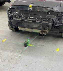
In order to place your target frame in the correct place, you will need to find the centerline of the vehicle by placing a plumb bob on the front and rear vehicle emblems and marking the floor below them. Once this is done, you can shoot a laser under the vehicle to connect the makings on the floor, and this will be your centerline. Using my ADAS software, I was instructed to mark out 672mm / 26.46" to the left of the centerline for point “M” and the same distance to the right of the centerline for point "N" (Figure 4). This would be my forward marks placed near the rear of the vehicle.
Using a second laser device, I placed a laser line down even with my front centerline mark at the front of the vehicle and shot another laser with the same unit to the rear of the vehicle, placing a laser target at a distance of 6,727mm / 264.84" to the rear of the vehicle (Figure 5). This would be the distance back further away from the rear of the vehicle where my frame would have to be placed. My next step would be to move my laser at the rear of the vehicle and extend my centerline further back to meet with my rear laser target to establish two more floor markers. I again marked out 672mm / 26.46" to the left of the centerline for point "K" and the same distance to the right of the centerline for point "P" (Figure 6). It was quite a bit of work, but now I had my four markers set up behind the vehicle, so I was now ready to set up my frame machine to calibrate both rear side radar control modules.
I started with the right-side radar control module and used the laser on my frame machine to place a centerline from point "P", where my frame was sitting on, through point "N" at the back right rear of the vehicle. The laser was laying on the radar housing, so I knew I was set up properly with the frame, but I had to install my doppler simulator radar box target onto the frame and raise the frame target to a specified height of 1237mm / 48.7" from the shop floor (Figure 7).
Once this was all done, I was now ready to command the radar unit to accept pulses from the radar box to finalize the calibration, and eventually I was finished with one side. The left-side would be the same procedure after I have moved and set up the frame to the left rear side of the vehicle. Once the left side was aimed and calibrated, the codes went away, and there were no longer any error messages on the dash.
This was some journey just to get a simple light out on the dash, and being in the automotive industry, you just do not know what to expect with each car you encounter. I am now finding out that many other manufacturers are requiring both rear side modules to be replaced at the same time if their numbers have been superseded, or you will get a configuration error code in memory, especially if they are not programmable. You cannot rely on a parts counter person to tell you this when you purchase a new module because there are no notations in the parts system to alert them. All they can tell you is that there has been a superseded number. This can mean it’s an updated part, but the end user is the one who must always figure out if there are any compatibility issues.
My suggestions are to always look at the hardware and software numbers on the module prior to putting the part in place, or you may be taking that bumper off again. These rear blind spot systems work in stereo, and they must match in functionality. It is equally important that if you are reprogramming one side with the latest software, you should be updating software for the opposite side. That also goes for the calibration process because you could just calibrate one side only, but the proper way is to always do both sides, even if only one side of the car was repaired, and there are codes for only one side.
I hope this story has enhanced what you already knew, or what you did not know since this ADAS field is only going to get more interesting as time goes on.
About the Author

John Anello
Owner and operator of Auto Tech on Wheels
John Anello is the owner and operator of Auto Tech on Wheels, established in 1991 in northern New Jersey. He provides technical assistance and remote reprogramming with 21 factory PC-based scan tools. Driven by a passion for cars, John's business now services roughly 1,700 shops.