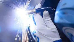
This past January at the Collision Industry Conference in Palm Springs, California, the Repair Process and Procedures Committee presentation dealt with the state of welding in the collision industry. They looked at the OEM certification programs, I-CAR’s welding qualification tests and equipment. Due to time constraints, they could not get into the real nitty gritty of welding.
This article will give you and your techs a better insight into the welding process. Before I start the discussion, please take this test.
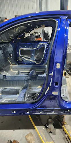
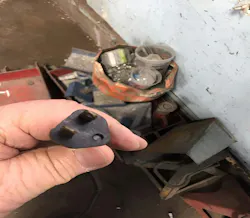
The picture depicts a “B” pillar on a 2021 Honda Accord that needs to be repaired or replaced. Pick the best option.
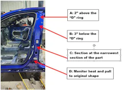
Honda’s Body Repair News September 2025 version 7's manual welding and sectioning guidelines advises the following:
Use of heat during body straightening and repair
When you are doing body straightening and repair procedures, follow these guidelines: Never use open flame to heat body panels. However, the use of induction heaters, copper stamp or heat guns is acceptable up to 1100 F (600°C).
Approved welding methods
MAG butt welding is an approved repair method for steel parts up to and including 780 MPa.
To minimize the heat-affected zone, butt welds on 780 MPa steel must be done as quickly as possible while maintaining adequate penetration. MAG plug welding is allowed on 1,500 MPa (hot stamp) steel parts in select locations only as specified in the model specific body repair manual. Welding instructions must be followed exactly as specified to ensure adequate weld strength.
The correct repair option for this test is to replace the entire “B” pillar with a new OEM part as per repair procedures from Honda. Next, I want to explain the reason WHY.
There are three major categories of steel utilized on today’s vehicles, which are mild steels, high strength steels (energy absorbing), and ultra-high strength steels (energy transfer). Steel's tensile strength is measured in MPa or megapascals, which indicates how much force it can withstand before failing. 1 MPa equals 145 psi (pounds per square inch). Mild steels go up to about 270 MPa, high strength steels up to 700 MP,a and ultra-high strength steels (UHSS) start around 900 MPa. UHSS parts are found in “A” and “B” pillar reinforcements, rocker reinforcements, floor and roof reinforcements, and door instruction beams. Let’s see what happens when the Honda rocker reinforcement is MIG-welded.
I took a sample from a Honda rocker reinforcement (1500 MPa) to test how welding would affect the strength. Honda states that there is no MIG/MAG welding on 1500 MPa parts except where a MIG plug weld is required.
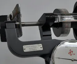
I got a reading of 45 HRC scale, which is 1480 MPa. I cut a slit in the reinforcement and removed a sample to test its strength before it was welded.
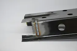
I welded the slit using stitch welds, not a continuous weld that would produce more heat than stitch welding (temperature at the weld site is approximately 2000 degrees F).
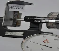
The HRC reading was 20, but the test chart for the anvil and diamond indenter starts at 24. To get a correct reading, I would have needed a different anvil and indenter, which I do not have. The reading of 24 translates into an MPa reading of 515 MPa. High strength steel starts at about 300 MPa. The MPa reading on a welded part was probably around the 300 MPa range. Being around the mild steel range at the welded area, another impact at that location would most likely cause the part to fail that could result in serious injury or even death.
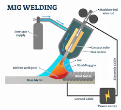
MIG welder basics
You will see the terms MIG and MAG welding. MIG welding stands for metal inert gas, and MAG stands for metal active gas. In the collision repair industry, a MIG welder is utilized using either argon/carbon dioxide (steel) or 100% argon (sluminum and MIG brazing). Let’s see how a MIG welder works.
Take a look at a battery. If you take the two battery jumper cables, attach them to the battery and touch them together, you will get sparks. If you hold the cables together, they will fuse. A MIG weld works on the same principle. The electrode wire is positive and the ground clamp is negative. And when the wire comes in contact with the base metal (now negative), an arc will form and the heats up the metal to around 2000 degrees F in the case of steel (known as a short arc transfer). The filler wire liquefies and mixes with the liquefied base metal, and both flow together (this is known as a fusion weld).
Once it cools down, there will be a solid weld. Before moving into the theory, I want to go over the parts of the welder, starting with the welding torch.
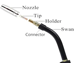
The nozzle directs the shielding gas into the weld puddle and helps protect it from contamination (water, oxygen, and nitrogen). The contact tip transfers electricity from swan to filler wire. The diffuser distributes the shielding gas to the weld site. Note: Always check that the contact tip is tight and the holes in the diffuser are open. Also make sure that the wire and contact tip are the same diameter (aluminum is the exception).
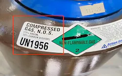
The shielding gas for steel is a mixture of 75% argon and 25% CO2 (carbon dioxide). Honda states the following in their repair manual:
“The preferred shielding gas is C20. A mixture of 80% argon (Ar) and 20% carbon dioxide (CO2), C20 produces a more stable arc, less weld spatter, and better weld quality/appearance. • C25 shielding gas, a mixture of 75% argon (Ar) and 25% carbon dioxide (CO2), is also acceptable. These are considered active gases because CO2 undergoes a limited reaction with the molten weld pool.”
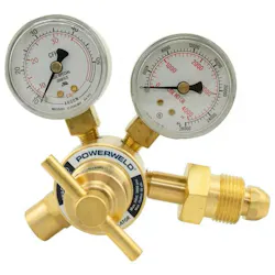
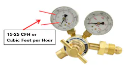
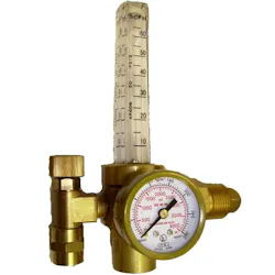
I have always upgraded my welders to a flow meter, which is easier to read and adjust. In the 20 years I have been doing the I-CAR welding tests, Only two have lost the pressure cover. When welding aluminum, you want 25 to 40 CFH, which is needed for proper arc cleaning action.
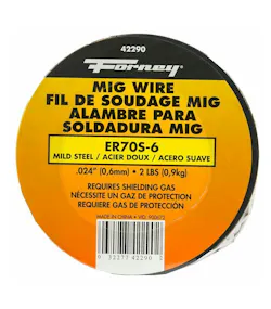
The welding wire widely used is ER70S6 for steel. Aluminum wire should be 4043, 4145, 5554, or 5356. MIG brazing calls for CuSi.3 and CuSi.A wire. Always consult the OEM repair information to determine the wire it calls for. For example, Honda states that ER70S-6 wire has a minimum tensile strength of 70 psi (483 MPa). This wire can be used when welding up to 440 MPa steel parts. When welding parts with high-strength steel of 590 MPa and higher, a high-strength welding wire must be used (see the web site for recommended wire).
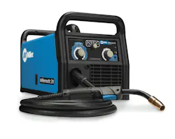
Do you know what a synergic welder is? A synergic welding machines has the ability to automatically set welding parameters based on factors such as wire type, diameter, and shielding gas. This is achieved by using a single knob to select the desired current intensity, wire feed speed, or plate thickness. In other words, you set the type of welding desired, the gas, and wire type. You then set the machine to the thickness of the metal, and the computer will set the amperage and wire speed for those parameters.
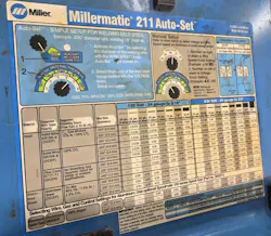
For the welders that are not synergic, there is usually a chart on the inside access panel that will give the technician a starting point.
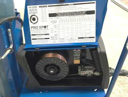
Let’s see how this works. The Millermatic 211 works on 120 or 220 volts. I will use 220 volts for this example. The wire for steel is ER70S6, wire diameter is .030 (.8MM), and the gas is argon and CO2. You find the line of steel diameter wire and move to the column that reads 18 gauge (1.2MM). The reading 4/50. 4 is the voltage and 50 is the wire speed. Set your welder, make a test weld, and adjust accordingly. Before welding, you need to check your extension cord.
A broken or missing ground on an extension cord is an OSHA violation and could cost you $1,500.00.
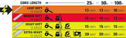
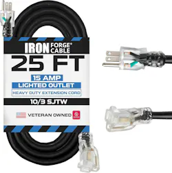
Most welders using 120 volts will max out at about 20 amps. The best choice for an extension cord is 10-gauge and no longer than 50 feet. 12-gauge works most of the time, but keep the length to a max of 50 feet. 14-gauge extension cord will restrict the necessary amperage to produce a good weld. Here are some products that will improve the welding process:
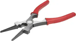
MIG pliers
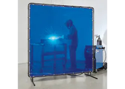
Welding screens and blankets
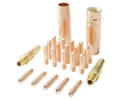
Extra consumables


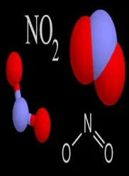
Let’s talk science
Water boils at 212 degrees F, and the temperature at the weld site is approximately 2000 degrees. Oxygen and nitrogen, along with water hitting 2000 degrees, will “explode” out of the weld site. Knowing these facts, let’s discuss gun travel angle.
A shielding gas is used to keep the molten weld pool from being exposed to the oxygen, hydrogen, and nitrogen in the air around the weld. Problems will occur from the reaction of these elements in the weld pool, including excessive spatter, and holes in the weld bead, known as porosity, that results in weaker welds.
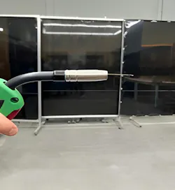
90 degrees horizontal
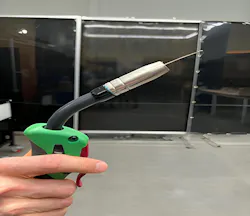
45 degrees from horizontal
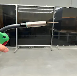
10-15 degrees from horizontal
The correct travel angle is 10 to 15 degrees from vertical or horizontal. Any angle larger will allow oxygen, water, and nitrogen to enter the weld site and produce a poor weld. A quick discussion is also necessary.

You cannot see electricity, so we will use water instead. Both operate using the same principles. Electricity employs amps and volts, and water uses volume and pressure. Water volume equates to amps with electricity, and water pressure equals volts with electricity. If you hook up a 10-foot hose to a hose bib and turn it on, you will have goodwater pressure and volume. Hook up a 100-foot hose, and the volume and pressure will drop. The same holds true with electricity; the longer the run from the electrical source, the more will be the voltage and amps drops, and that affects the welding process. Remember that the contact tip in the torch is where the wire “picks up” the electricity. The distance from the end of the nozzle to the metal surface is known as “stick-out.”
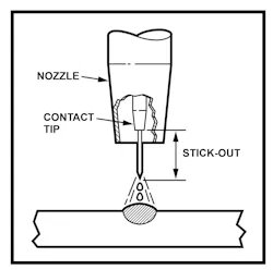
Stick-out
Electrode stick-out is the length of wire coming out of the contact tip of the welding gun. It affects the amount of amperage at the weld site. It is easier to use the tip of the nozzle for reference. Steel stick-out is 6-7mm, aluminum 10-12mm and MIG braze 15-17mm. When welding steel, too long of a stick-out produces a cold weld and too short, a very hot weld. We have looked at two welding parameters — gun angle and stick-out — with work angle the being the last I want to discuss.
Work angle is where you point the gun. It can range from 45 degrees to 90 degrees, depending on what is being welded.
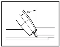
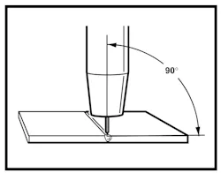
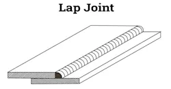
The root of the weld is where you want the fusion to take place.
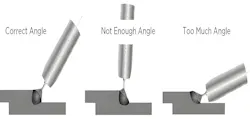
When welding an overlap joint on today’s vehicles, a work angle of 60 to 70 degrees is used. On truck frames, 45 degrees is probably the most utilized. Now, let’s have one last discussion on the difference between pushing the puddle and dragging the puddle.
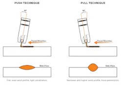
The welding puddle is pushed ahead of the torch when pushing, and pulled behind it when dragging. The difference in direction can impact penetration depth and width. Pushing is better for thinner materials and dragging for thicker materials. Pushing the puddle will produce a weld with deeper penetration and dragging will result in better side penetration. It should be noted that when welding aluminum and MIG braze, we only push. Let’s look at a couple of welds that are performed at an I-CAR steel welding test.
The plug weld
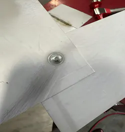
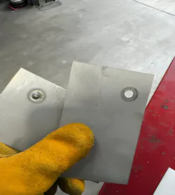
This plug weld passed all the visual parameters and destructive tests.
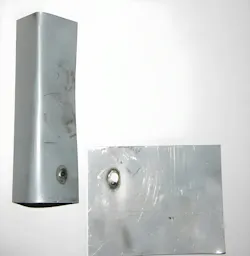
When pulled apart, the plug weld left a hole in the top coupon, which indicates there was no weld penetration to the top coupon (the diameter did not meet the 8 mm minimum). To pass the destructive test, the plug weld needs to remove metal from the bottom piece of sheet metal (the minimum tearout is a 5 mm hole).
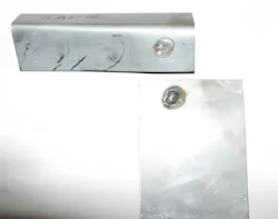
This weld failed the destructive test because there was also no penetration to the bottom coupon even though the weld passed the visual inspection for size (the weld did fill the 8 mm hole completely).
The open butt joint
This weld is performed with a work angle of 90 degrees, and the weld should look the same on front and backside of the panel.
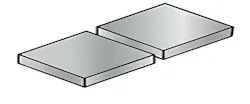
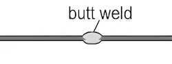
I want to repeat myself about checking the welder before you start welding.
- Check the plug on the machine and extension cord
- Check the welding gauge
- Check the nozzle, diffuser, and contact tip
- Check the settings on the welder
- Check OEM welding procedures for the vehicle that is being welded
- Make a practice weld and conduct a destructive test.
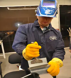
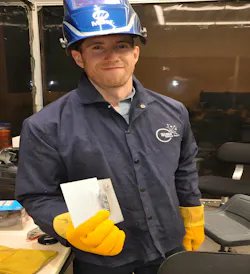
Personal protective equipment for welding
The most important part of the welding process is the safety of your technicians.
OSHA PPE required welding regs:
1910.134(a)(2)
A respirator shall be provided to each employee when such equipment is necessary to protect the health of such employee. The employer shall provide the respirators which are applicable and suitable for the purpose intended. The employer shall be responsible for the establishment and maintenance of a respiratory protection program, which shall include the requirements outlined in paragraph (c) of this section. The program shall cover each employee required by this section to use a respirator.
1910.252(b)(2)(i)(C)
All operators and attendants of resistance welding or resistance brazing equipment shall use transparent face shields or goggles, depending on the particular job, to protect their faces or eyes, as required
1910.252(b)(3)
Protective clothing - General requirements. Employees exposed to the hazards created by welding, cutting, or brazing operations shall be protected by personal protective equipment in accordance with the requirements of § 1910.132 of this part. Appropriate protective clothing required for any welding operation will vary with the size, nature and location of the work to be performed
1910.134(e)(1)
General. The employer shall provide a medical evaluation to determine the employee's ability to use a respirator, before the employee is fit tested or required to use the respirator in the workplace. The employer may discontinue an employee's medical evaluations when the employee is no longer required to use a respirator.
OSHA 1910.134(f)(2) explicitly states fit testing must be conducted "at least annually thereafter."
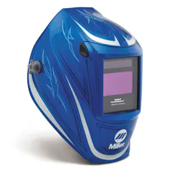
Wear a good auto darkening with a welding helmet with a sensitivity setting. (Set for shade 10). It should have an attachment method for a magnifier lens.

Wear gloves designed for MIG welding.
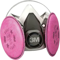
Wear a particulate respirator.
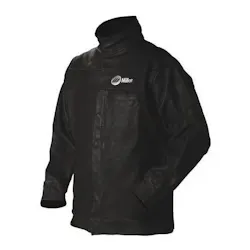
Wear a quality welding jacket, safety glasses, hearing protection, and sturdy shoes and pants.
About the Author
 Toby Chess
Toby Chess
A Hall of Eagles recipient, Toby Chess is known throughout the collision repair industry for his training for I-CAR and SCRS, and technical presentations at CIC meetings. He estimates he's taught more than 7,000 hands-on I-CAR welding classes, plus 15,000 other live classes in multiple states.
An advocate for body shops and their consumers, Toby has been awarded the SCRS Lifetime Achievement and Industry Achievement Awards, Collision Industry Individual Service Award, Humanitarian Award, and the ABRN Leadership award.