What you will learn:
• Always Identify the terminal designation
• ECUs test circuits for integrity
• Comparing a suspect circuit's operation to a known-good is an efficient strategy
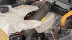
I was called to a body shop with a complaint on a 2019 Honda Civic with an airbag light on. The vehicle was in a recent front-end collision while it was parked on the street. Most of the damage was located on the driver’s side of the vehicle where the left crash sensor was located. The vehicle was still in the final stages of repair, so I had great accessibility to the front harness and both crash sensors (Figure 1). The shop did replace the left front crash sensor as a precautionary measure, along with a new crash sensor connector that was damaged from the impact.
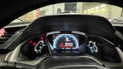
When I arrived at the shop, I started the vehicle and noticed the Air Bag warning message on the instrument cluster (Figure 2). I proceeded to hook up my Scan tool to do a full scan report of the entire vehicle. The only trouble code stored in the vehicle was for the Air Bag Control Module, and it was a Code B0090-87 “No Signal from Left Front Crash Sensor” (Figure 3). The crash sensor was a two-wire sensor, in which each wire lead directly back to the Air Bag Control Module. It was now time to put down my scan tool and gather up some handheld testing equipment to validate the crash sensor wiring.
Finding the path to enlightenment
My first tool of choice to check the wiring was my Power Probe. This handy tool will connect to the battery positive & negative leads and provide a screen to display voltage levels in the vehicle electrical system. The beauty of this tool is that it can be used as a quick continuity tester. If the wire being tested (on a crash sensor, with the key on) is an open circuit, then you will get a blank screen with no voltage signal. I do caution you that you are only using this tester as a voltage meter at this point. So, DO NOT apply the rocker switch to feed power or ground into the circuit you are testing. If so, you will damage the airbag control module.
I did get a reading out of each wire of about 0.1 volts (Figure 4). I knew that the wires were not open circuits. I also went one step further and made sure that the connector pins were fully seated in the connector and that they made good contact with the crash sensor pins.
So, I validated the wiring and the connector. But now, I was turning my attention to a possible wrong application crash sensor in the vehicle, or an issue with the new crash sensor. The only way to further test the system would be to use a scope to see how the Air Bag Module was testing the sensor. I wanted to hook up my scope to the right-side crash sensor first so I could learn from a known- good circuit. I could then test the problem-side after I had learned the testing strategy within the waveform.
I unplugged the right-side crash sensor and placed my leads (RED to the outer-right terminal, BLACK to the outer-left terminal, with the connector lock facing up). (Figure 5). When testing like circuits you always need to make sure you use the same test procedures on both devices to validate good test results.
I set up my scope on a 5-second graph across the screen and set up my voltage scale at +/- 14 volts. I did not know what kind of scope pattern to expect but this set-up was enough range to catch a wave. I had a shop employee turn the key on while I was viewing the scope and here, came the pattern. I immediately stopped the screen to see what was displayed (Figure 6).
What’s good for the goose…
This whole event only lasted about three seconds. You can see a small voltage bump on the initial start, then after one second the Air Bag Module sent a variable 8-8.5 peak voltage signal. Then the signal voltage was pulled away and dropped back down to zero. This was the module’s way of testing the internal circuitry of the crash sensor. Now that I had the information I needed, it was time to test the problem side.
I set up my scope leads in the exact orientation of the other side to keep my testing valid. I again set up my scope and had the shop employee turn on the ignition while I was watching my scope pattern. Then, something weird happened! The pattern was identical, but it was upside down (Figure 7). The only thing that could cause this was the wires feeding the crash sensor were reversed. I can't even blame the tech who replaced the connector end because the manufacturer made both crash sensor wires the identical color and at this point, it was a 50/50 crapshoot. I turned off the key, removed the wires from the connector, reversed the pin locations, secured both crash sensor connectors, and started the vehicle. All was good :)
Connector integrity is a huge issue when it comes to repairs in our industry. It has become a more common practice to repair damage to a wiring harness rather than replace an entire vehicle sub-harness for just minor damage to a connector. You can find many companies out there now that only require a picture of your connector (along with its application,) and you will be guaranteed a new connector match that can be sold with or without the wiring already built into the connector. Some of these connectors may come prewired with wires of the same color. It is up to the shop to wire the connector correctly, solder the connections, and heat-shrink tube the connectors to prevent moisture intrusion. This will guarantee an acceptable practice to meet most manufacturer requirements.
The biggest issue you will face is the orientation of the wiring pins within the connector (Figure 8). If you are dealing with a thermistor for a two-wire sensor, then the wires could be installed in either terminal within the connector, because a thermistor (such as a coolant sensor) is only looking for a 5-volt reference feed and a reference ground to be placed across the sensor unit, in either direction.
Things can now get a little complicated if you are dealing with a two-wire SRS Crash Sensor or even a two-wire ABS Magneto Resistive Digital Output type of wheel speed sensor. These devices are constantly being tested by the Control Modules they service on every key cycle, and the testing voltage is directional through the sensor circuitry. You must know which wire goes to the proper pin, even if the manufacturer uses the same color for each wire (Figure 8). Hopefully, this helps to shed light on how the manufacturers did not create an easy repair road for us. I hope you have learned from this article, and on your next two-wire repair you will not be bitten by the “Orientation Lion.”


